Explore Collections Explore The Collections
You are here: CollectionsOnline  /  Designs for firebox, stove, chimney piece and flues (2)

Browse

  • image Image 1 for SM (46) volume 74/35 (47) volume 74/36
  • image Image 2 for SM (46) volume 74/35 (47) volume 74/36
  • image Image 1 for SM (46) volume 74/35 (47) volume 74/36
  • image Image 2 for SM (46) volume 74/35 (47) volume 74/36

Reference number

SM (46) volume 74/35 (47) volume 74/36

Purpose

Designs for firebox, stove, chimney piece and flues (2)

Aspect

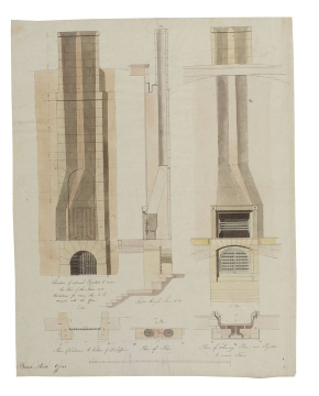
46 Plan on Line C D, Plan on Line A B, Plan on Line E F, sections and elevation for cellar firebox and stove 47 Plans, sections and elevations for north-wall chimney piece and flues

Scale

(46) bar scale of 1/14 inch to 1 foot (47) bar scale of ½ inch to 1 foot

Inscribed

46 as above, Bank Stock Office, a key of A B C D E F and K Fire Place / L Smoke / M Cast Iron / Plates to form / the divisions / for Warm Air / N 2 inches brick / work to prevent / the Smell of the / Iron.... / O 4 inches Cavity / to contain the / heat of the body / of the stove / P Box to clean / the Stove, G Brick Wall / H Bricks 4 inches / thick to form / divisions for / the Conduit / for Cold Air / I Opening to / admit Cold Air / J Revolutions of / Cold Air, Q 4 inches Cavity / for Warm Air / R Windsor bricks / on Edge..... / S Bars to cover / the top of the / Stove / T Circular brick / Pier / V holes to convey / the Warm Air / U, No 8 (six times), No 12 (three times), 14 (three times), 15 (three times), 16 (twice), 9 (six times), No 10 (eleven times), 17 (three times), 18 (four times), 20 (three times), 21 (four times) 47 Bank Stock Office, Elevation of external Projection to receive / Flues of the Stoves and / Revolutions for warm Air to be / conveyed into the Office, Section through Line G H, 1st Plan, Plan to Cellar of B S Office, 3rd Plan, Plan of Flues, 2nd Plan, Plan of Chimney Piece and Projection / to receive Flues

Signed and dated

  • (46-47) datable to 1792-93

Medium and dimensions

(46) Pen, pale red pen, sepia, burnt sienna and blue washes on wove paper with one fold mark (523 x 649) (47) pen, pencil, pale red pen, sepia, yellow ochre, burnt sienna washes on wove paper with one fold mark (643 x 508)

Hand

(46-47) attributed to William Lodder (assistant 1789-?) or Charles Ebdon (assistant 1791-1792)

Notes

According to Willmert drawing 46 shows the hall's heating system as executed: a brick firebox in the centre of the cellar producing warm air channeled into the free-standing stove above. This is most certainly the heating system fabricated by A. Ramellie for £138:18:0 and installed 'in the cellar' in April 1793
In drawing 46 the firebox also appears linked to the hypocaust system shown in drawing 45, via the duct, in blue wash, on the edge of the left section. According to the plan in drawing 45, this duct would lead to the north wall flues.
Drawing 47 depicts the chimney piece and accompanying flues built at the north end of the Bank Stock Office, as well as a locked, grated entrance into the cellar below. The flues connected to the hypocaust system depicted in drawing 45, conducting hot air and smoke generated by the firebox in the centre of the cellar, as seen in drawing 46, up through the north wall and out of the building. Drawing 22 clearly shows the chimney piece and cellar door in relation to the built hall.
It also appears that the hot air pipes embedded in the north wall and running exposed across the front of the chimney piece might have helped warm the hall. Additionally or alternatively, the chimney piece may have been a working fireplace, holding a bed of hot coals in a raised grate.

Literature

(46) A.T. Bolton, The Works of Sir John Soane, 1924, p. 64; (46-47) T. Willmert, 'Heating methods and their impact on Soane's work: Lincoln's Inn Fields and Dulwich Picture Gallery', Journal of Society of Architectural Historians, 52/1, March 1993, (46) pp. 31-32, fig. 6; (47) p. 32, fig. 8

Level

Drawing

Digitisation of the Drawings Collection has been made possible through the generosity of the Leon Levy Foundation

If you have any further information about this object, please contact us: drawings@soane.org.uk

Sir John Soane's collection includes some 30,000 architectural, design and topographical drawings which is a very important resource for scholars worldwide. His was the first architect’s collection to attempt to preserve the best in design for the architectural profession in the future, and it did so by assembling as exemplars surviving drawings by great Renaissance masters and by the leading architects in Britain in the 17th and 18th centuries and his near contemporaries such as Sir William Chambers, Robert Adam and George Dance the Younger. These drawings sit side by side with 9,000 drawings in Soane’s own hand or those of the pupils in his office, covering his early work as a student, his time in Italy and the drawings produced in the course of his architectural practice from 1780 until the 1830s.

Browse (via the vertical menu to the left) and search results for Drawings include a mixture of Concise catalogue records – drawn from an outline list of the collection – and fuller records where drawings have been catalogued in more detail (an ongoing process).