Browse
Reference number
Purpose
Aspect
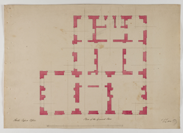
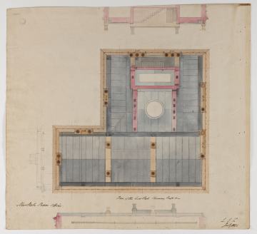
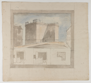
132 Plan of the Lead Flats Chimney Shafts &c with sections through the roofline looking north, east and south; (verso) rough block plans and perspective from Duke Street
Scale
Inscribed
132 as above, New State Paper Office
Signed and dated
- July 1831
(131, 132) L.I.F. / July 1831
Medium and dimensions
Hand
Watermark
Notes
Level
Sir John Soane's collection includes some 30,000 architectural, design and topographical drawings which is a very important resource for scholars worldwide. His was the first architect’s collection to attempt to preserve the best in design for the architectural profession in the future, and it did so by assembling as exemplars surviving drawings by great Renaissance masters and by the leading architects in Britain in the 17th and 18th centuries and his near contemporaries such as Sir William Chambers, Robert Adam and George Dance the Younger. These drawings sit side by side with 9,000 drawings in Soane’s own hand or those of the pupils in his office, covering his early work as a student, his time in Italy and the drawings produced in the course of his architectural practice from 1780 until the 1830s.
Browse (via the vertical menu to the left) and search results for Drawings include a mixture of Concise catalogue records – drawn from an outline list of the collection – and fuller records where drawings have been catalogued in more detail (an ongoing process).


