Browse
Reference number
Purpose
Aspect
Scale
Inscribed
Signed and dated
- Undated, but datable March-April 1689
Medium and dimensions
Hand
Watermark
Notes
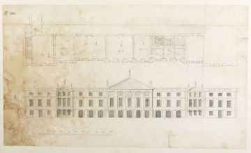
The canted staircase bay drawn in graphite alongside the two-flight staircase on the west side of the new frontage would have provided separate access to the Tudor ‘Princess Mary apartments’ in the area of the turreted square corner pavilion drawn on Hawksmoor’s second survey plan (AS, IV.5; Fig. 00). The overlaid Privy Garden range on this survey corresponds closely in overall length with this frontage (310 feet compared with 307 feet) but does not show the intermediate pavilions within the outer pavilions. Hawksmoor’s hand is indicated by the handwriting of the notes, in particular the 5 with its incomplete lower loop and the ‘S’-shaped 1, both characteristic of his handwriting in the late 1680s and 1690s.
The frontage scales at 307 feet, an enlargement of the 260 feet length of the Privy Garden front adopted for Grand Project 2 and just five feet short of the executed dimension (312 feet). The extra 42 feet from Grand Project 2 was achieved by extending the frontage west and east of the centre line of the Privy Garden (see the survey plan in Thurley 2003, pl. 140). As noted above, this meant that the west range of the new Privy Court would have overlapped part of the Great Hall.The lengthening of the Privy Garden front was the result of a need to accommodate all the king’s apartments in one range. The plan shows the bed in dotted outline in the fifth room from the west end of the block. Preceding it, from west to east, would have been the Guard Chamber, the Ante Room, the Presence Chamber and the Withdrawing Room. Beyond lay his closets and an undimensioned room, possibly intended as as a Council chamber, with shared access to the queen’s apartments.The elevation indicates a loggia at ground floor level across eleven arched bays. This compares with the fifteen-bay loggia on the elevation in Grand Project 2 (section 2, 2; 110/7) and the thirteen-bay loggia on the near final elevation (section 4, 1; 110/9). The height of the first floor above ground level is 12 feet 6 inches, a foot less than in the other preliminary elevation from this phase in the design (4; 110/14). The latter is closer to the executed height and may indicate its later date.
Literature
Level
Sir John Soane's collection includes some 30,000 architectural, design and topographical drawings which is a very important resource for scholars worldwide. His was the first architect’s collection to attempt to preserve the best in design for the architectural profession in the future, and it did so by assembling as exemplars surviving drawings by great Renaissance masters and by the leading architects in Britain in the 17th and 18th centuries and his near contemporaries such as Sir William Chambers, Robert Adam and George Dance the Younger. These drawings sit side by side with 9,000 drawings in Soane’s own hand or those of the pupils in his office, covering his early work as a student, his time in Italy and the drawings produced in the course of his architectural practice from 1780 until the 1830s.
Browse (via the vertical menu to the left) and search results for Drawings include a mixture of Concise catalogue records – drawn from an outline list of the collection – and fuller records where drawings have been catalogued in more detail (an ongoing process).

