Browse
Reference number
Purpose
Aspect
Scale
Inscribed
Signed and dated
- datable to November 1785 see note below
Medium and dimensions
Hand
Notes
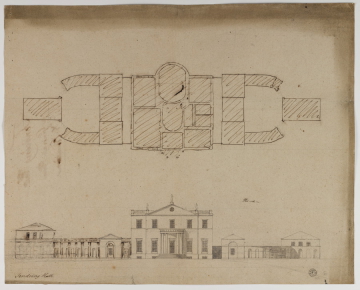
The purpose of the drawing is the finalising of the design for the offices. Each consists of a one-bay pavilion (next to the house) joined by a curved and niched wall to a three-bay, two-storey pavilion with matching niched wall. The left-hand elevation, not fully drawn out, has been amended so that, for example, the niches are framed by pilasters and a frieze added.
A finished plan with elevation of the house and offices at the Victoria & Albert Museum (see P. du Prey, Sir John Soane, 1985, in series of 'Catalogues of architectural drawings in the Victoria and Albert Museum', catalogue 110, plate 22)) show much the same design for the house (though without the balustraded parapet and statues) as the drawing catalogued above. The elevations to the offices differ and in particular they are each placed on a slope, giving the house greater eminence and ensuring that the roofs and enclosing walls to the offices defer to the mass of the centre. Visually it would have been a great improvement though the differing floor levels within the kitchen and stables wings might have posed a problem. The idea of a sloping site for the service wings is added in pencil on the right-hand side of the above Soane Museum drawing. The V&A drawing is inscribed 26 November 1785 and probably the Soane Museum drawing was made shortly before that date.
Level
Sir John Soane's collection includes some 30,000 architectural, design and topographical drawings which is a very important resource for scholars worldwide. His was the first architect’s collection to attempt to preserve the best in design for the architectural profession in the future, and it did so by assembling as exemplars surviving drawings by great Renaissance masters and by the leading architects in Britain in the 17th and 18th centuries and his near contemporaries such as Sir William Chambers, Robert Adam and George Dance the Younger. These drawings sit side by side with 9,000 drawings in Soane’s own hand or those of the pupils in his office, covering his early work as a student, his time in Italy and the drawings produced in the course of his architectural practice from 1780 until the 1830s.
Browse (via the vertical menu to the left) and search results for Drawings include a mixture of Concise catalogue records – drawn from an outline list of the collection – and fuller records where drawings have been catalogued in more detail (an ongoing process).

