Browse
Reference number
Purpose
Aspect
Scale
Inscribed
Signed and dated
- 28 December 1692
Medium and dimensions
Hand
Watermark
Notes
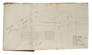
The order relating to this plan is on fo. 132 v. (28 September 1692). Wren's response is on fo. 134 (28 December 1692). The area that is the subject of the petition in the order (that of Arnold Thompson) is outlined in red ink on two of its four sides.The scale bar itself is marked out as a bar of parallel lines, to create 10 feet divisions vertically and horizontally. The sloping parallel lines in the right-hand box facilitate the calculation of areas in 1/10 parts of 10 feet square. The device is found on sectors and slide rules in the period (see A. Gerbino and S. Johnston, Compass & Rule: Architecture as Mathematical Practice in England, 1500-1750, p. 00, fig. 00).
Literature
Level
Sir John Soane's collection includes some 30,000 architectural, design and topographical drawings which is a very important resource for scholars worldwide. His was the first architect’s collection to attempt to preserve the best in design for the architectural profession in the future, and it did so by assembling as exemplars surviving drawings by great Renaissance masters and by the leading architects in Britain in the 17th and 18th centuries and his near contemporaries such as Sir William Chambers, Robert Adam and George Dance the Younger. These drawings sit side by side with 9,000 drawings in Soane’s own hand or those of the pupils in his office, covering his early work as a student, his time in Italy and the drawings produced in the course of his architectural practice from 1780 until the 1830s.
Browse (via the vertical menu to the left) and search results for Drawings include a mixture of Concise catalogue records – drawn from an outline list of the collection – and fuller records where drawings have been catalogued in more detail (an ongoing process).

