Browse
Reference number
Purpose
Aspect
Scale
Inscribed
Signed and dated
- November 2nd: 1814.
Hand
Watermark
Notes
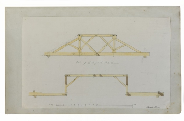
Evidently, Soane had to create a structure with a flat top because it was to support a central chimney. Thus the supporting timbers had to be strong enough to bear the chimney's weight, so scissor braces were used for support across the width of two (of the four) sides between queen posts (as shown on the upper section of this drawing). The two shorter sides on the plan (SM volume 76/42) are those represented.
The lower section of the drawing shows the two longer spans between queen posts, shown on the plan (SM volume 76/42). The lower section of the drawing ties the beams in, rather than providing much structural support. It measures about 17 feet across, which is approximate to the longer span between the queen posts shown on SM volume 76/42. SM volume 76/43 shows a detail of the roof's corner in plan and elevation.
SM volume 76/44 shows the plan - a two room, one-storey structure. One room was presumably a preparation space (with fireplace) whilst the other would have held the oven. The roof-beam dimensions roughly correspond to the plan.
Literature
Level
Sir John Soane's collection includes some 30,000 architectural, design and topographical drawings which is a very important resource for scholars worldwide. His was the first architect’s collection to attempt to preserve the best in design for the architectural profession in the future, and it did so by assembling as exemplars surviving drawings by great Renaissance masters and by the leading architects in Britain in the 17th and 18th centuries and his near contemporaries such as Sir William Chambers, Robert Adam and George Dance the Younger. These drawings sit side by side with 9,000 drawings in Soane’s own hand or those of the pupils in his office, covering his early work as a student, his time in Italy and the drawings produced in the course of his architectural practice from 1780 until the 1830s.
Browse (via the vertical menu to the left) and search results for Drawings include a mixture of Concise catalogue records – drawn from an outline list of the collection – and fuller records where drawings have been catalogued in more detail (an ongoing process).

